

 English
 中文简体
 русский
 Français
 Español
 Deutsch

Warp Knitting Machine for Carbon Fiber Textile: Specs, Stitching and Buying Guide
2026-10-07
Content
- 1 What a Warp Knitting Machine for Carbon Fiber Textile Actually Does
- 2 Why Carbon Fiber Rewrites the Operating Rules
- 3 Machine Architecture: Needles, Guide Bars and Weft Insertion
- 4 Gauge, Working Width and Areal Weight: The Numbers That Decide Your Fabric
- 5 Tow Tension Control and Fiber Handling
- 6 Stitching Damage, Binder Powder and Resin Compatibility
- 7 Multiaxial or Biaxial: Choosing Layer Architecture
- 8 What to Put in a Purchase Specification
- 9 Acceptance Testing: What to Measure Before You Sign
- 10 Procurement Risks and the Real Cost of Ownership
- 11 Maintenance, Consumables and Uptime
- 12 How to Shortlist Suppliers Without Wasting Months
- 13 Scaling from Sample Rolls to Serial Production
Two quotations land on the same desk. Both offer a multiaxial warp knitting line, both list the same working width, both promise high output. One buyer signs and discovers six months later that the fabric carries resin-rich windows between tows and a stitch line that eats 4 percent of tensile strength. The other buyer asks a different set of questions first, and gets a line that runs the same way on month one and month eighteen.
The difference is rarely the brand. It is whether the machine was specified as a stitching platform for brittle, conductive, high-modulus fiber, or as a general textile machine that happens to be fed carbon.
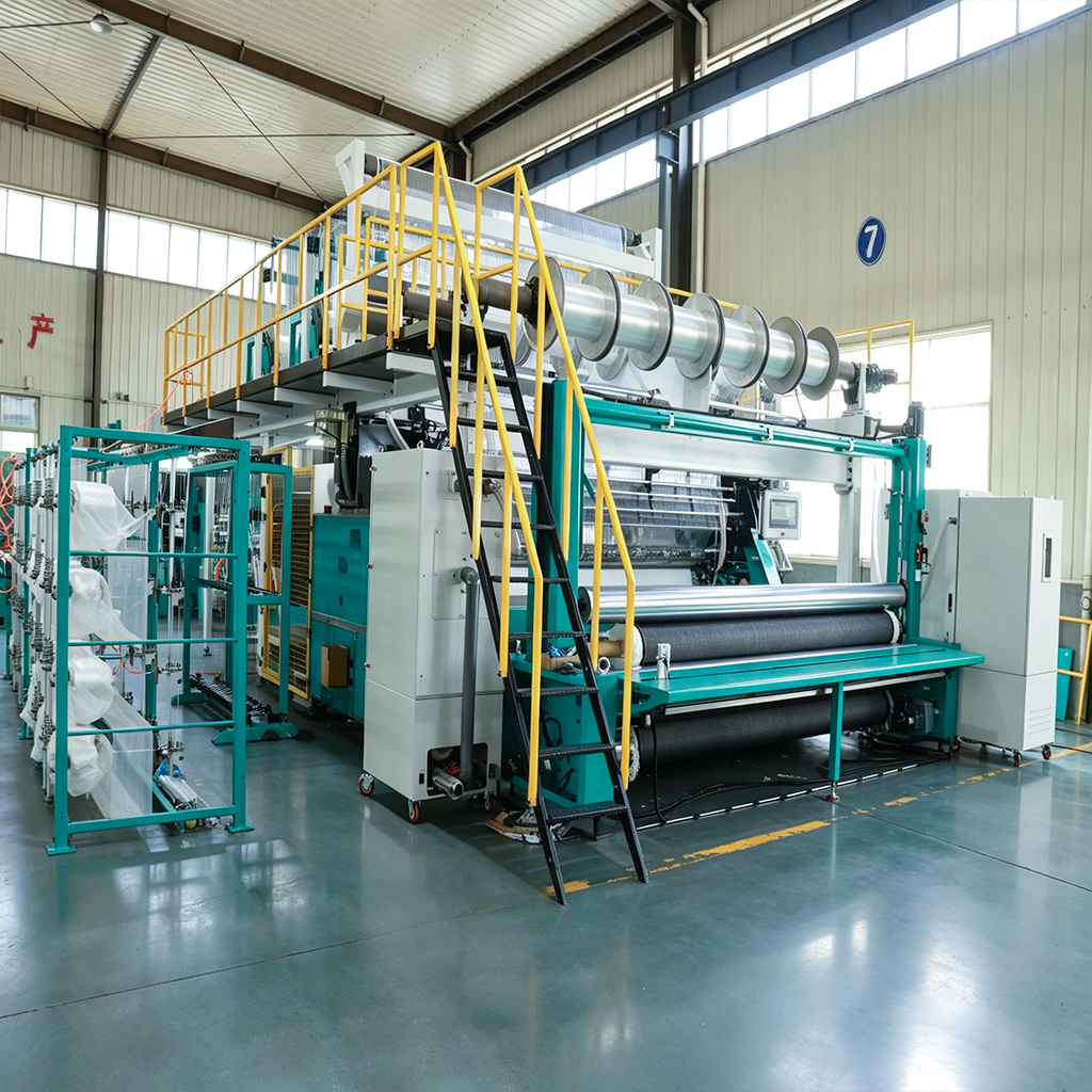
A warp knitting machine for carbon fiber textile works on a simple principle: oriented carbon tows are held in place by a light binding yarn stitched through them, producing a dry non-crimp fabric (NCF) that later goes through resin infusion or preforming. Everything that matters follows from that sentence. The tows must stay straight, the binding yarn must do its job with the least fiber damage possible, and the machine must hold both conditions for thousands of metres.
This guide covers what these machines actually do, which parameters decide whether your fabric is sellable, the numbers worth writing into a purchase specification, and the checks that separate a working line from an expensive one.
What a Warp Knitting Machine for Carbon Fiber Textile Actually Does
In apparel warp knitting, the machine makes the fabric from yarn it knits into loops. A carbon-capable multiaxial warp knitting machine is closer to a stitching frame. It takes already-formed reinforcement layers and ties them together so they can be handled, cut, stacked and infused without the tows sliding apart.
A typical build stacks four layers:
- A 0-degree layer from warp beams, fed in machine direction under controlled tension.
- A 90-degree weft layer inserted by a carriage travelling across the working width.
- Two diagonal layers at +45 and -45 degrees, fed from inclined creels or traverse systems.
- A binding yarn from one or more guide bars, forming a pillar or tricot stitch line through the stack.
The machine is judged on four outputs, in this order of commercial importance: layer orientation accuracy, tow position and spread, fiber damage introduced by stitching, and areal weight consistency across and along the roll. Speed comes fifth, because a line running at 30 metres per hour with 2 percent waste beats a line at 50 metres per hour that produces out-of-tolerance fabric nobody will buy twice.
Where the value sits
Everything upstream of the needles is where the money is spent. Warp beam quality, tension control, tow guidance, weft carriage repeatability and stitch pattern selection account for most of the fabric quality you will sell. The needle line itself is a small part of the machine, but it is the part that determines how much strength you lose.
For buyers comparing machine families across materials, this overview of how fiberglass, chemical fiber and carbon fiber machines differ is a useful starting point before technical discussions begin.
Why Carbon Fiber Rewrites the Operating Rules
Carbon fiber is not a difficult yarn in the way a hairy staple yarn is difficult. It is difficult because it does not forgive. Standard modulus carbon fiber has an elongation at break around 1.5 to 2.0 percent and essentially no plastic deformation. A single sharp edge, a tension spike, or a guide eyelet with a worn ceramic insert does not stretch the fiber, it snaps filaments.
Four properties drive most machine design decisions for carbon processing:
- Brittleness. Every contact point in the yarn path becomes a potential damage site. Guide eyelets need large radii, polished ceramic surfaces and correct alignment with the tow direction.
- Low friction tolerance combined with high friction reality. Carbon sizing formulated for epoxy compatibility is often tackier than textile sizing, so drag builds up quickly over long yarn paths.
- Electrical conductivity. Broken filaments and dust are conductive. They migrate into cabinets, bearings and sensors, and they create static that makes tows balloon and cross. Proper grounding, dust extraction and antistatic measures are not optional extras.
- Heavy linear density. A 12K standard modulus tow runs about 800 tex, a 24K about 1,600 tex, a 48K about 3,200 tex. These are thick, stiff bundles compared with a 167 dtex polyester stitch yarn, and they behave more like flat tapes than like yarns.
The practical consequence is that a carbon line is specified around low, stable tension and minimal, controlled contact. Machines designed for glass at high speed often run carbon acceptably at reduced speed, but the specification logic is different: on carbon you are buying tension stability and damage control, and you are paying for them in guide bar count, servo response and yarn path design.
Fuzz is a measurement, not an annoyance
Broken filaments show up as fuzz and dust long before they show up as a strength loss in a test report. Two useful field indicators: the quantity of fuzz collected at the needle line per shift, and the number of visible broken filaments per metre of fabric under a low-power microscope. Track both from the first trial roll. A rising trend means a worn guide, a drifting tension setpoint or a stitch pattern that is too aggressive for the tow count.
Machine Architecture: Needles, Guide Bars and Weft Insertion
A carbon multiaxial line breaks down into six subsystems, and each one carries a specific risk if it is under-specified.
Needle line and stitch formation
Compound needles are the usual choice on technical textile machines because they allow a closed, well-controlled stitch at speed with reduced yarn stress compared with latch needles. For carbon work the more important detail is the geometry around the needle: sinker design, trick plate alignment, and how the binding yarn is presented. A binding yarn that is dragged across the tow surface rather than placed cleanly into the stitch will abrade filaments on every course.
Guide bars
Two to four guide bars is the normal range on NCF machines. One or two bars carry the binding yarns and do the actual stitching; additional bars can inlay yarns without stitching through them. Each bar usually has its own warp beam and its own servo-controlled let-off, so that stitch yarn tension and reinforcement tow tension are set independently. This independence is a specification point worth confirming in writing.
Warp beam feeding of the 0-degree layer
The 0-degree tows come off beams that may weigh several hundred kilograms and carry hundreds of individual tows. Tension must stay even across the full width as the beam diameter shrinks from full to empty. Closed-loop let-off with dancer or load-cell feedback handles this; a simple mechanical brake does not, and the resulting variation shows up as waviness in the finished laminate.
Weft insertion and diagonal layers
A weft carriage lays the 90-degree layer, often from a magazine creel with accumulators to keep the tow under constant tension as the carriage accelerates and decelerates. The diagonal layers come from inclined creels and traverse units that lay tows at fixed angles. Angle tolerance of plus or minus 1 degree is a realistic target on a well-maintained machine; plus or minus 3 degrees is a warning sign, because it changes the effective stiffness of the finished part by more than most customers accept.
Take-off and batching
Fabric is pulled, edge-trimmed and wound under controlled tension. Take-off tension matters more than it looks: uneven take-off pulls the layers out of alignment and can introduce crimp in the weft. Constant-tension batching with adjustable winder tension is a low-cost option that prevents a high-cost quality problem.
Control and data logging
Recipe management, per-position tension monitoring, and automatic logging of stitch length, speed and tension during each roll are the features that make qualification and traceability possible. If your customers ask for process data, this is the subsystem that supplies it.
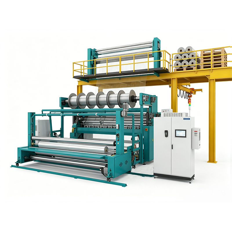
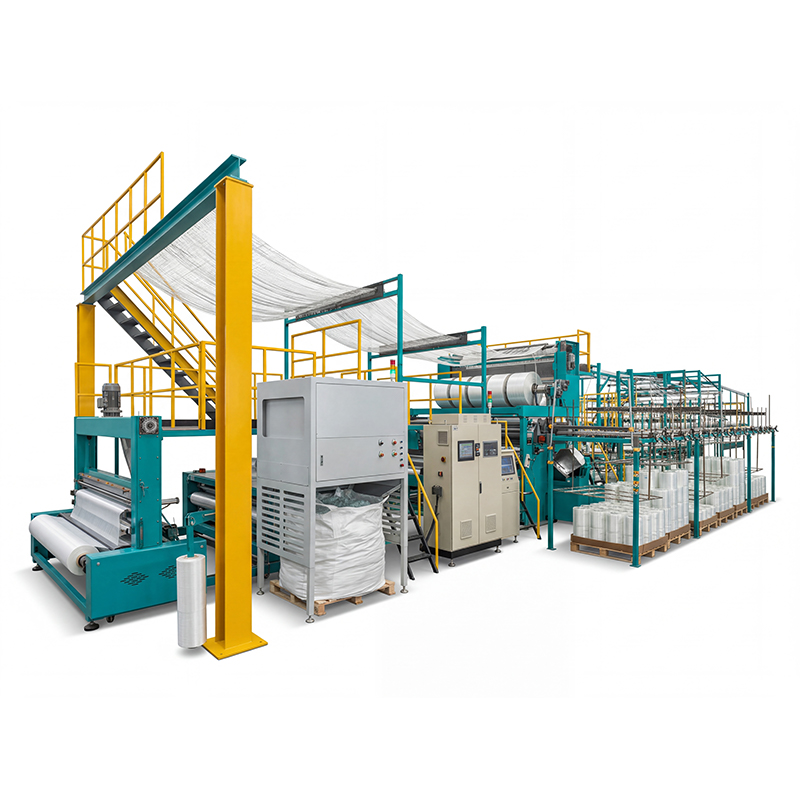
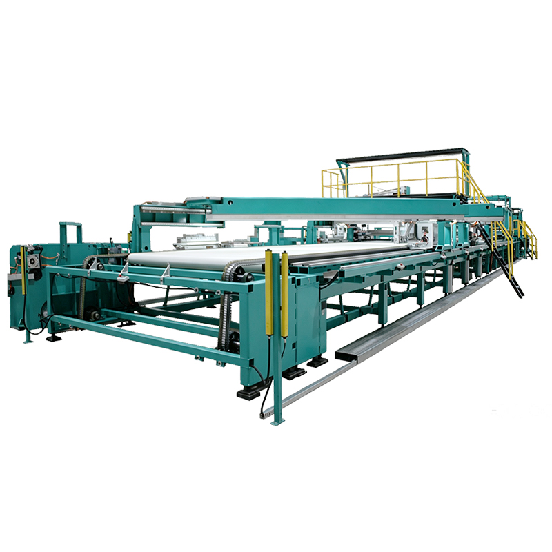 YRS3-3M-C Carbon Fiber Multiaxial Warp Knitting MachineDedicated carbon NCF production with multi-layer, multi-angle weft laying, process monitoring and traceability for demanding composite reinforcement fabrics.View Product →
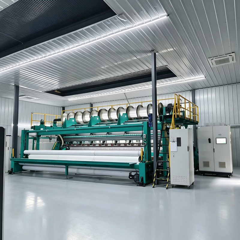
The YRS33MC carbon fiber multiaxial warp knitting machine represents this architecture applied specifically to carbon reinforcement: a multiaxial layout with dedicated tow handling, aimed at producing dry carbon NCF rather than adapting a general-purpose frame.
| Pattern | How it forms | Typical binding yarn use | Effect on the preform | Watch-outs |
|---|---|---|---|---|
| Closed pillar (chain) | Same needle stitched every course | Low, roughly 4 to 8 g/m2 depending on gauge and stitch length | Highest stability per gram of yarn, narrow stitch line | Concentrated needle load, faster needle wear |
| Open pillar | Alternating needles each course | Lower, roughly 3 to 6 g/m2 | Lighter and more drapeable fabric | Less tow security; more care needed in cutting and handling |
| Tricot | One-needle lateral underlap | Higher, roughly 6 to 10 g/m2 | Wider stitch line, better resistance to tow separation | More crimp and more resin-rich area |
| Cord or satin inlay | Long underlaps covering several needles | Variable | Can tie down thick stacks or add surface effects | Harder to keep tow alignment consistent |
| Weft inlay without stitching | Yarn laid in without being looped | None for the inlaid yarn | Adds straight yarns with no crimp | Must be secured by a separate stitching bar |
Gauge, Working Width and Areal Weight: The Numbers That Decide Your Fabric
Three parameters determine whether a machine can make your product at all. Everything else is optimisation.
Gauge
Gauge is expressed in needles per inch, written as E. Carbon NCF lines commonly sit between E5 and E12, with the exact choice tied to tow format and target fabric weight. Finer gauge gives more stitch lines per inch, which improves dimensional stability and allows thinner fabric, but it also means more needle penetrations per square metre and therefore more potential fiber damage. Coarser gauge reduces stitching density and damage but limits how evenly the stack is tied down.
Working width
Typical working widths fall between about 1,000 mm and 2,540 mm, with 1,270 mm and twin 1,270 mm configurations being common because they fit downstream cutting and preforming equipment. Always confirm usable fabric width after edge trimming, not nominal width. A 20 mm difference in usable width changes the nesting efficiency of every part your customer cuts.
Areal weight and layer coverage
Layer weight is arithmetic, not magic. Weight in grams per square metre equals tow linear density in grams per metre divided by tow pitch in metres. A 12K tow at 800 tex is 0.8 g/m. Lay those tows at 4.2 mm pitch and you get about 190 g/m2 in the 0-degree layer. At 6.3 mm pitch you get about 127 g/m2. This single calculation tells you whether a proposed gauge and tow combination can deliver the fabric your customer specified.
| Tow format | Linear density | Pitch 4.2 mm (about E6) | Pitch 6.3 mm (about E4) | Notes |
|---|---|---|---|---|
| 12K | About 800 tex | About 190 g/m2 | About 127 g/m2 | Most flexible format; spreading to 5 to 8 mm helps close gaps |
| 24K | About 1,600 tex | About 380 g/m2 | About 254 g/m2 | Heavier, stiffer bundle; spreading strongly recommended |
| 48K | About 3,200 tex | Not practical | About 508 g/m2 | Best for thick, cost-driven builds; gap risk is high |
The gap problem nobody quotes for
If the tow is narrower than the pitch, gaps appear between adjacent tows. Those gaps become resin-rich channels in the finished laminate, and they are a common reason for rejected first articles. Two fixes exist: choose a finer pitch so the tows cover the width, or add a tow spreading unit that flattens each bundle. Spreading also improves surface uniformity and reduces the thickness variation of the dry preform. Ask any supplier how their proposed configuration guarantees coverage on your specific tow at your specific areal weight, and ask for a sample roll that demonstrates it.
Buyers who want to review the wider equipment family before narrowing down can browse the carbon fiber machine range alongside comparable glass and chemical fiber platforms.
Tow Tension Control and Fiber Handling
Tension is the single variable with the largest influence on fabric quality, and the hardest to verify from a brochure.
Recommended working tensions for carbon tows are low. For a 12K standard modulus tow, a typical operating window is roughly 0.02 to 0.1 cN/dtex, which translates to approximately 1.6 to 8 newtons per tow. Multiply that by several hundred tow positions and the machine frame is holding a few hundred newtons of steady load, with transient spikes whenever the beam diameter changes or the carriage reverses.
What to specify
- Per-position tension variation within one beam held to plus or minus 10 percent of setpoint.
- Beam-to-beam and position-to-position variation held to plus or minus 15 percent.
- Closed-loop let-off with compensation for beam diameter, not a fixed brake setting.
- Monitoring and logging per beam, so drift is detected before fabric is scrapped.
The reason tolerance matters commercially is waviness. Where tension varies, tows wander sideways and in-plane waviness develops. Waviness reduces compressive performance disproportionately, and it is invisible on a visual inspection of the dry roll. Buyers who measure only areal weight and angle often miss it entirely until mechanical testing.
Yarn path discipline
Count the contact points between beam and needle. Every one should have a large radius, a polished ceramic or coated surface, and alignment that avoids side-loading the tow. Where a supplier offers an unusually short or straight yarn path, that is usually a deliberate damage-reduction decision rather than a cost saving. Ask which surfaces were selected for carbon and what their replacement interval is.
Beam quality is half the battle
A poorly warped beam with crossed tows, uneven tension or inconsistent beam density cannot be corrected at the knitting machine. If you buy beams from a third party, qualify them the same way you qualify the machine: measure tension at a minimum of ten positions across the width and check tow separation along the full length. Rejecting a bad beam is far cheaper than sorting out-of-tolerance fabric six weeks later.
Stitching Damage, Binder Powder and Resin Compatibility
Stitching holds the preform together at a cost. The binding yarn introduces crimp, occupies volume that would otherwise be fiber, and creates resin-rich channels along the stitch line. Typical binding yarn consumption ranges from about 2 to 10 g/m2 depending on pattern, gauge, stitch length and yarn count, with 76 to 167 dtex polyester being a common choice and glass or soluble yarns used for specific processes.
Published work on stitched NCF consistently shows a modest reduction in in-plane properties, in the low single digits to around 10 percent for some layups, offset by a substantial improvement in interlaminar fracture resistance and, critically, in handleability. The engineering task is to keep the penalty small and predictable. Practical levers include:
- Choosing the lightest stitch pattern that still holds the tow architecture through cutting and layup.
- Keeping stitch length and binding yarn tension low enough that the yarn lies on the surface rather than cutting into the tow.
- Maintaining sharp, correctly set needles and replacing them on a schedule based on metres run, not on visual failure.
- Polishing or replacing guide elements at the first sign of fuzz increase.
Binder powder and its own tolerance problem
Many NCF lines add a thermoplastic or epoxy binder powder to stabilise the preform during cutting and stacking. Add-on levels of roughly 3 to 8 percent by weight are common, and the tolerance that matters is scatter uniformity, not average pick-up. Uneven powder creates tacky patches, resin-rich spots and inconsistent drape. A scattering unit with closed-loop weight control and a clean dosing path keeps the add-on repeatable roll after roll.
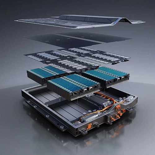 YAS Auto Powder-Spreading Machine for Composite Preform StabilisationApplies resin powder to glass or carbon fabric, supporting uniform add-on and stable pre-shaping before cutting, stacking or downstream molding.View Product →
The YAS auto powder spreading machine belongs to the same production sequence for preform stabilisation, and the questions that apply to it are identical to those for the knitting line: what is the add-on tolerance, how is it measured, and how stable is it over a full shift.
Resin compatibility is a system question
The binding yarn and the sizing on the carbon tows must be compatible with the resin the customer uses. Polyester stitch yarns with standard epoxy-compatible sizing are the common pairing. Soluble or thermoplastic stitching yarns serve processes where the binding yarn should disappear or become part of the matrix. Silicone-based lubricants, release agents and general workshop contamination are the enemies here, because they cause delamination or poor bonding that only appears after testing. Keep the knitting area clean and separate from any silicone-containing process.
Multiaxial or Biaxial: Choosing Layer Architecture
The architecture decision comes before the machine decision, because it drives creel count, guide bar count and realistic production speed.
Biaxial
Biaxial fabric uses two orientations. The common configurations are 0/90 for warp-and-weft constructions and plus or minus 45 for shear-resistant constructions. Fewer layers mean fewer creels, less tow handling, shorter yarn paths and higher achievable speed. Setup and changeover are simpler, and waste at start and stop is lower.
Multiaxial
Multiaxial fabric adds diagonal layers, typically 0, plus 45, 90 and minus 45. The result is a more balanced, more drapeable preform with better conformability over curved tooling, at the cost of more creels, more tow positions, more tension setpoints to control and lower throughput. Angle accuracy becomes harder to hold because four layer systems must be coordinated.
The practical compromise
Most industrial lines are specified so that the same frame can run biaxial and multiaxial configurations by using or idling creel positions and guide bars, with the recipe library holding a separate setup for each product. If your product mix spans both, insist that changeover time between configurations is documented and demonstrated, not estimated. A changeover that takes two shifts will quietly kill your flexible capacity.
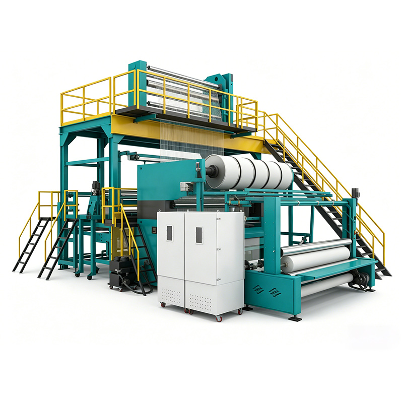
Because the underlying stitching principle is shared across reinforcement types, a multiaxial platform designed for one fiber family often informs the carbon version. The glass-oriented multiaxial machines in the same catalogue illustrate that continuity. The YRS33M multiaxial warp knitting machine is representative of that family.
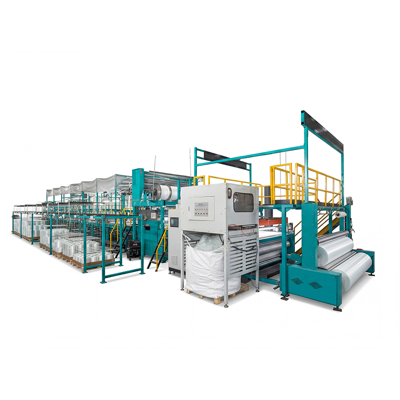 YRS3-3M Multi-Axial Warp Knitting Machine for Glass and BasaltProduces multi-axial glass and basalt reinforcement fabrics with servo weft laying; compare it with the dedicated YRS3-3M-C carbon version.View Product →
When comparing a carbon-specific machine against a glass multiaxial machine, focus the technical questions on the differences that affect carbon: tow guidance radii, tension range and resolution, dust handling, and the maximum tow count the creels and beams are designed to accept.
What to Put in a Purchase Specification
A specification that lists only width and speed invites a quotation that fits the numbers and not the job. The table below sets out the parameters worth naming, with target values and the way to verify each one.
| Parameter | Target to ask for | Why it matters | How to verify |
|---|---|---|---|
| Usable working width | State nominal and post-trim width separately | Drives nesting efficiency downstream | Measure trimmed fabric on trial roll |
| Gauge | Matched to tow format and target areal weight | Determines minimum pitch and coverage | Confirm with coverage calculation and sample |
| Guide bars | 2 to 4, each with independent servo let-off | Separates stitch yarn and tow tension control | Run with two different tension setpoints |
| Tension window | Per-tow setpoint with plus or minus 10 percent across width | Waviness and layer alignment depend on it | Measure 10 positions with a hand-held tension meter |
| Areal weight tolerance | Plus or minus 3 percent within a roll, plus or minus 5 percent roll to roll | Directly affects laminate thickness and resin uptake | Cut and weigh 10 samples per roll |
| Layer angle tolerance | Plus or minus 1 degree in steady running | Changes effective stiffness of finished parts | Measure from roll photographs or by cutting templates |
| Binding yarn consumption | Stated in g/m2 for each pattern | Small percentages become large annual costs | Weigh yarn feed over a measured length |
| Speed | Quoted on your fabric, not on the lightest possible build | Speed claims rarely survive dense layups | Ask for a timed run at your areal weight |
| Dust and fuzz control | Extraction at the needle line, filtration down to about 5 micrometres | Conductive dust damages electronics and fabric | Inspect filters after a full shift |
| Data logging | Per-roll log of speed, tension and stitch length | Needed for traceability and qualification | Export a log file during FAT |
Acceptance Testing: What to Measure Before You Sign
Factory acceptance testing is where a supplier demonstrates capability and where a buyer catches problems cheaply. Four to eight hours of continuous running at production speed is a reasonable minimum, and it should produce a roll you keep and test independently.
Measurements to run during the test
- Areal weight: cut samples at five positions across the width, at the start, middle and end of the roll. Ten samples minimum.
- Layer angles: check at least three locations per roll for each diagonal layer.
- Tow pitch and gap count: count visible windows per metre across the width.
- Stitch length and binding yarn consumption: weigh the yarn consumed over a measured fabric length.
- Tension logging: confirm that logged tension stayed inside the specified window, and check where any excursions occurred.
- Fuzz and broken filament count: sample fabric under low magnification and record the baseline.
- Machine behaviour: noise, vibration, temperature of drives, power draw, and any alarm history.
Tests worth paying for
Independent mechanical testing on the trial roll is money well spent. Fiber volume fraction, tensile properties per layer, and interlaminar fracture toughness give you a baseline to compare against future production. If the numbers move three months later, you will know whether the machine changed or the supplier of the tow changed.
Site acceptance test
Plan a second test after installation, typically 30 days into production. At that point you can check reproducibility across several beams, uptime percentage, consumable consumption per 1,000 metres, and the actual response time of technical support. Hold a portion of payment against these results.
Procurement Risks and the Real Cost of Ownership
The machine is not the line. Budget for the whole system: warp beams and creels, spreading units if coverage requires them, dust extraction, humidity control, beam storage, a beam trolley, a fabric inspection table, initial spare parts, freight, installation and commissioning, operator training, and the engineering time to develop recipes for each product.
Risks that appear after the order
- Speed claims that do not hold at your areal weight. A machine specified for light biaxial fabric will run slower on a dense four-layer build, and the commercial case built on the brochure figure collapses.
- Binding yarn consumption underestimated. At 8 g/m2 on a 600 g/m2 fabric, that is more than one percent of material mass plus scrap, and it affects cost and laminate properties.
- Gauge or pitch mismatch discovered late. If the fabric shows windows, the fix may be a spreading unit or finer gauge, not an adjustment.
- Spare part lead times. Ask which parts are held in stock, in what quantity, and what the guaranteed dispatch time is.
- Control and recipe support. A machine only runs as well as its recipe library and the willingness of the supplier to help develop new ones.
- Calibration drift. Tension sensors and powder dosing scales drift. Ask how calibration is scheduled and how it is verified.
- Documentation and language. Electrical drawings, maintenance manuals and PLC documentation should be supplied in a language your maintenance team reads.
Cost drivers worth modelling
Three numbers dominate operating cost: downtime cost per hour, waste percentage at start and stop, and consumable cost per kilogram of fabric. Start and stop waste of 3 to 10 percent is normal on a new line and should fall with practice; if it does not, the setup procedure or beam quality is the usual cause. Needle and guide consumption on carbon will always exceed glass, because abrasion is inherent to the fiber.
Maintenance, Consumables and Uptime
A carbon line needs a maintenance routine built around abrasion and dust rather than around hours run alone.
Daily checks
- Inspect and clean extraction filters; conductive fiber dust builds faster than expected.
- Check tension readings at several positions against a hand meter.
- Look for fuzz accumulation at the needle line and around guide eyelets.
- Confirm the fabric surface has no new windows or streaks.
Weekly and monthly checks
- Verify creel alignment and guide eyelet condition; replace any insert showing a groove or polish mark.
- Check needle condition across the full working width, not just a spot check in the middle.
- Clean and inspect weft carriage rails and accumulators.
- Verify powder dosing weight against a calibration sample if a scattering unit is part of the line.
- Review logged data for tension drift or speed loss trends.
Consumables to stock
Needles, sinkers, guide needles, ceramic eyelets, thread guides, drive belts, tension sensors and electronic spares. Keep usage records per beam and per fabric type; needle life on carbon is typically counted in hundreds of production hours rather than thousands, and the exact figure is machine and pattern specific. A spare needle set kept on site is cheaper than a halted production week.
Uptime above 90 percent in two-shift operation is a reasonable target for a mature line with a stocked spares cabinet and a trained maintenance technician. Getting there requires discipline in the first year, not luck.
How to Shortlist Suppliers Without Wasting Months
Supplier selection should be based on demonstrated process fit, not on brochure specification.
Run a structured comparison
- Send a real tow sample and a real fabric specification, including areal weight, layer architecture, binding pattern and any mechanical requirements.
- Request a trial roll, not a demonstration on the supplier's preferred easy build.
- Ask for the trial data: tension logs, areal weight measurements, angle measurements and photographs of the fabric surface.
- Test the trial roll independently, ideally in the same laboratory that will test your production.
- Visit a running installation if possible, and ask the operator about downtime and support response.
Scorecard criteria
- Process fit on your specific tow and areal weight.
- Trial results versus your acceptance limits.
- Engineering ability to modify guide paths, creels or controls for your product, including customised components.
- Spare parts stocking policy and dispatch commitments.
- Service footprint and realistic response time.
- Training content and duration, including recipe development.
- Documentation quality and completeness.
- Terms on warranty, retention and performance guarantees.
Be sceptical of quotations that list width, gauge and maximum speed only. Those three numbers can be met by machines that will not produce your fabric to specification, and the gap only becomes visible after the deposit is paid.
Scaling from Sample Rolls to Serial Production
Once the first line is running, the priority shifts from capability to repeatability. Do a simple throughput calculation to check whether one line, two lines or a wider line is the right answer.
Take a working width of 1,270 mm at 25 metres per hour with 85 percent efficiency over 6,000 production hours per year. Usable area per year is roughly 1.27 m multiplied by 25 m/h, multiplied by 6,000 h, multiplied by 0.85, which is approximately 161,900 square metres. At a 400 g/m2 fabric weight, that is close to 65 tonnes of dry reinforcement per year before waste. If your required volume is higher, the answer may be a wider machine, an additional shift, or a second line, and each option has a different capital and labour profile.
Build the systems around the machine
- Standardise beam specifications and beam suppliers so tension behaviour is predictable.
- Create a recipe library with locked parameters and a documented change-control process.
- Define quality control limits and record them roll by roll.
- Train operators on fault recognition, especially fuzz, windows, angle drift and weight drift.
- Set a planned maintenance calendar with consumable replacement intervals based on data.
Reproducibility, not peak performance, is what makes a carbon NCF business profitable. The second machine should copy the first one's recipe and maintenance discipline exactly.
A warp knitting machine for carbon fiber textile is specified around restraint: restrained tension, restrained contact, restrained stitch aggressiveness. The parameters that decide success are the coverage arithmetic between tow density and pitch, the tension window across the full working width, the stitch pattern and its damage cost, and the repeatability of all three over thousands of metres.
The buying sequence follows from that. Define the fabric first, run the coverage calculation, then specify gauge, width and guide bar configuration. Ask for a trial roll on your tow and your areal weight, measure it independently, and hold payment against results. Verify tension stability, weight tolerance, angle accuracy and fuzz levels on the machine before it ships, and again after 30 days of production.
Do those things and the decision becomes defensible. Skip them and the machine you buy will be judged by the fabric it produces, which is the only specification that ever really mattered.
News
-
A fabric engineer compares two swatches on a cutting table. One is a lightweight mesh that holds its shape, resists runs, and stretches very little. The other is a soft jersey that curls at the edges...
READ MORE -
Three quotations land on the same desk for the same polyester nonwoven line, and on paper they look interchangeable. Each is priced per metre of working width. Each quotes a similar top speed. Each c...
READ MORE -
Which Machine Category Matches Each Technical Fiber and Fabric Goal A warp knitting machine is the primary production platform for technical fiber textiles across fiberglass, chemical fiber, and carbo...
READ MORE -
What Is a Tricot Warp Knitting Machine A tricot warp knitting machine is a textile production machine that forms fabric by looping many parallel yarns fed from a warp beam, with each needle working i...
READ MORE
-
Contact Info.
+86-198 5534 1617
+86-134 0158 3002yuanyang@yywarpknitting.com 699#, Shengzhi West Rd, Lvcheng Town, Danyang City, Zhenjiang City, Jiangsu Province, China

-
QR Code
-
Quick Links
Home About Products Manufacturing Customization News Contact -
Product List
Machine for Chemical Fiber Textile Machine for Fiberglass Textile Machine for Carbon Fiber Textile -
About Us
Company Profile Factory Gallery Value-added Service
Copyright © 2026 Changzhou Yuanyang Electromechanical Technology Co., Ltd. All Rights Reserved.
Custom Warp Knitting Machine Manufacturers
