

 English
 中文简体
中文简体 русский
 Français
 Español
 Deutsch
FC Chopped Stitch Bonding Machine for High-Uniformity Fiberglass Textile Production
2026-09-23
Content
- 1 1. Overview of the FC Chopped Stitch Bonding Machine
- 2 2. How the Three-in-One Production Process Works
- 3 3. Advantages for Fiberglass Textile Manufacturers
- 4 4. Reference Performance and Production Capacity
- 5 5. Product Applications
- 6 6. Engineering and Manufacturing Strengths
- 7 7. Configuration and Line Integration
- 8 8. Installation, Commissioning, and Acceptance
- 9 9. Maintenance, Training, and Long-Term Support
- 10 10. Comparison with Alternative Reinforcement Production Methods
- 11 11. Recommended Data for a Technical Proposal
- 12 12. Frequently Asked Questions
- 12.1 What products can the FC Chopped Stitch Bonding Machine manufacture?
- 12.2 What type of fiber does the standard machine use?
- 12.3 What fabric weight range is available?
- 12.4 How is fabric uniformity controlled?
- 12.5 What is the standard chopped fiber length?
- 12.6 Which working width should be selected?
- 12.7 What are the reference output figures?
- 12.8 Is the machine suitable for pipeline rehabilitation fabric?
- 12.9 Can the machine be integrated into an existing workshop?
- 12.10 Can the machine produce carbon fiber or synthetic fiber products?
- 12.11 What installation support is provided?
- 12.12 What training is available?
- 12.13 What should be included in the acceptance test?
- 12.14 How does the FC machine compare with a biaxial warp knitting machine?
- 12.15 How can production downtime be reduced?
- 13 13. Conclusion
- 14 References
- 15 Product: FC Chopped Stitch Bonding Machine
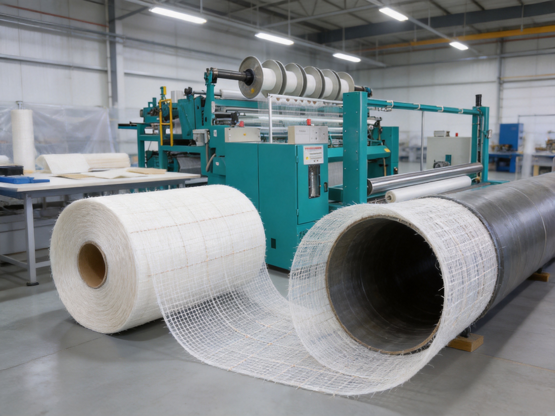
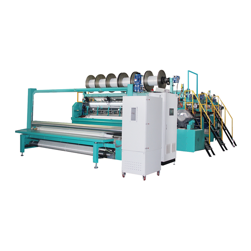
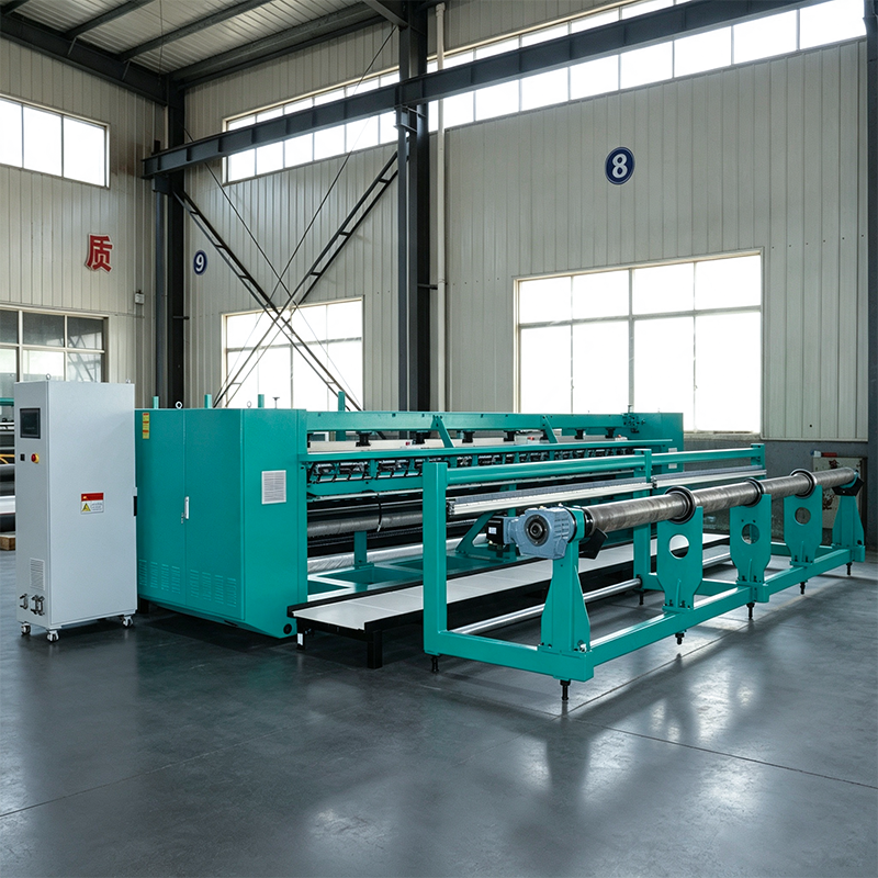
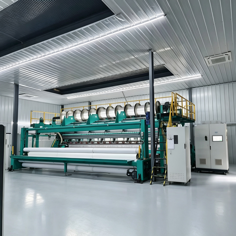
The FC Chopped Stitch Bonding Machine is an integrated production system for manufacturing chopped strand mats, grid composite mats, and pipe rehabilitation fabrics from glass fiber roving. It combines three essential operations—fiber chopping, web conveying, and stitch bonding—within one continuous process. By integrating these stages into a coordinated line, the machine reduces intermediate handling, improves production consistency, and provides an efficient route to non-oriented fiberglass reinforcement materials.
Designed for industrial textile manufacturers, composite material producers, and pipeline rehabilitation fabric suppliers, the machine is built around a single guide bar loop-forming system, an independent chopping unit, and a servo-controlled conveying mechanism. Chopped glass fibers are cut to a standard 50 mm length, evenly distributed across the working width, and reinforced with knitting yarn to form a stable, flexible, and process-ready fabric.
The machine is manufactured by Changzhou Yuanyang Electromechanical Technology Co., Ltd., a Chinese textile machinery enterprise specializing in warp knitting equipment, stitch-bonding machinery, biaxial and multiaxial warp knitting machines, carbon fiber textile equipment, web laying systems, and customized textile production lines. Its engineering approach combines mechanical design, electrical control, process development, fabrication, installation, and after-sales support in one coordinated service system.
1. Overview of the FC Chopped Stitch Bonding Machine
Traditional chopped strand mat production may require separate stages for fiber cutting, web formation, transfer, consolidation, and reinforcement. Each additional transfer point can introduce variation in fiber distribution, increase labor requirements, and make process control more difficult. The FC Chopped Stitch Bonding Machine addresses these issues by placing chopping, conveying, and stitch bonding into a continuous production architecture.
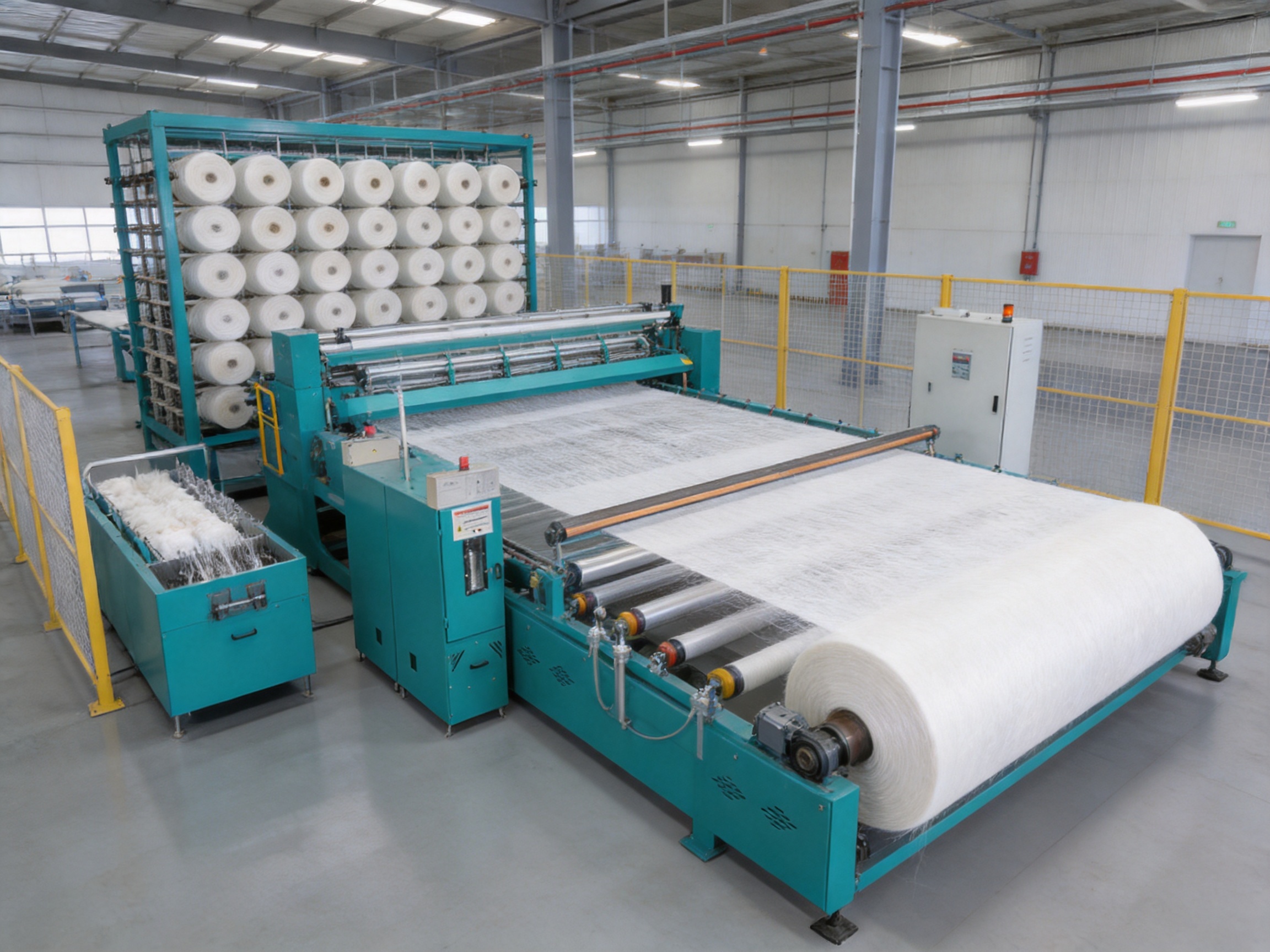
Glass fiber roving is fed into an independent chopping unit, where it is cut into controlled lengths. The chopped strands are then transferred by a servo-controlled conveying system. The conveyor distributes the material into an even, non-oriented web before the web reaches the stitch-bonding section. A single guide bar forms loops with knitting yarn, locking the loose fibers into a finished mat.
This configuration is particularly suitable for manufacturers that need a stable nonwoven reinforcement structure rather than a woven, unidirectional, or biaxial textile. The fibers are distributed without a fixed directional orientation, allowing the finished material to provide balanced reinforcement and consistent resin uptake in many composite and lining applications.
The machine supports fabric weights from 50 to 900 g/m². The actual weight depends on the fiber tex, chopping rate, material feed, conveyor speed, stitch density, knitting yarn specification, and production settings. This broad range allows one machine platform to serve both relatively light reinforcement materials and heavier industrial mats.
Core Product Characteristics
- Applicable fiber: glass fiber roving.
- Standard chopped fiber length: 50 mm.
- Finished fabric weight range: 50–900 g/m².
- Reinforcement method: stitch bonding with knitting yarn.
- Guide bar arrangement: single guide bar loop formation.
- Working widths: 3300 mm and 3800 mm.
- Machine speed range: 50–1300 r/min.
- Uniformity tolerance: within ±5% under specified operating conditions.
- Main applications: chopped strand mat, grid composite mat, and pipeline rehabilitation fabric.
The machine is not simply a high-speed fiber cutter or a conventional warp knitting machine. Its value lies in the coordination of separate process functions. The chopping unit prepares the fiber, the conveying system manages distribution, and the stitch-bonding section provides structural integrity. The result is a production line designed around the final fabric rather than around one isolated machine function.
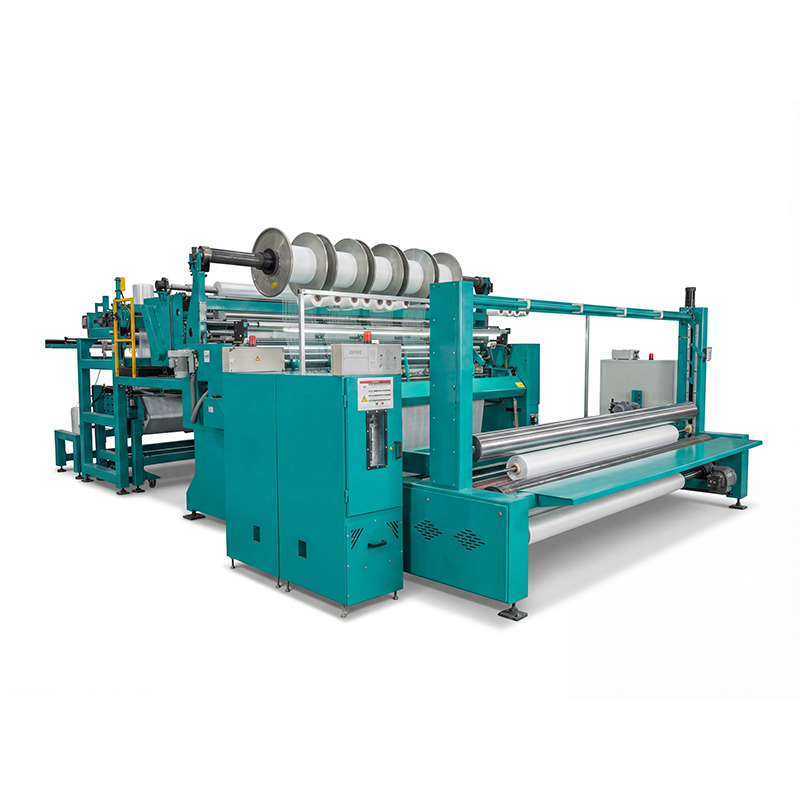
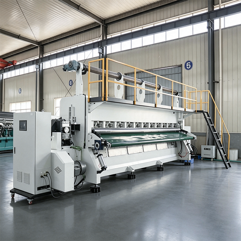
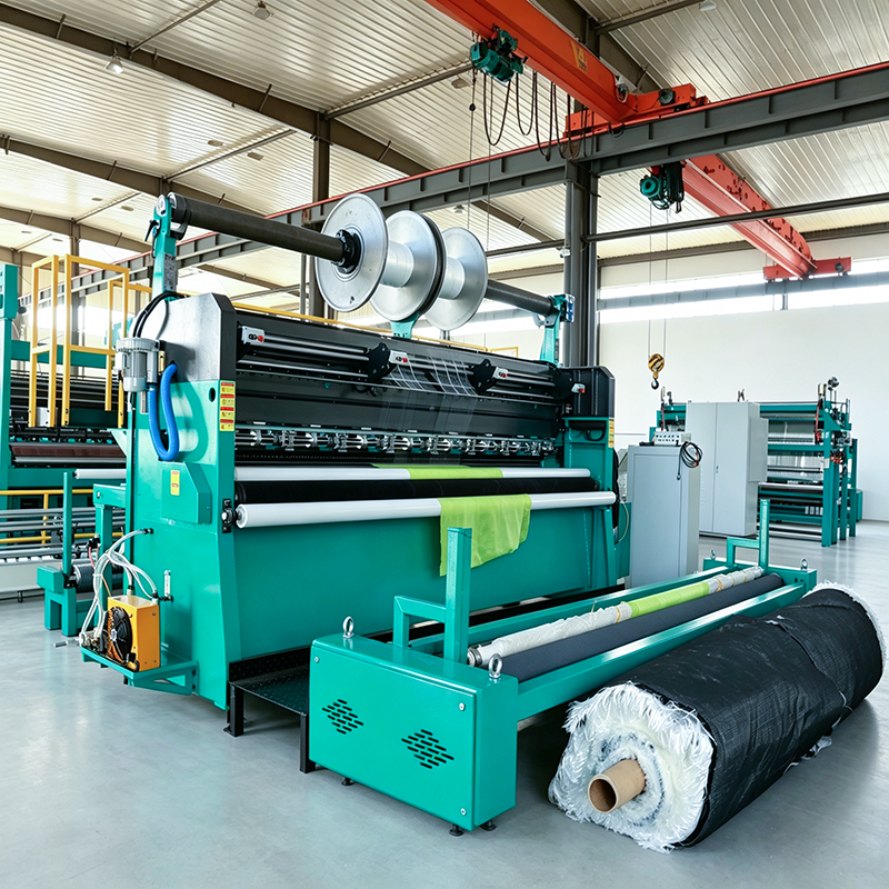
FC Chopped Stitch Bonding Machine
2. How the Three-in-One Production Process Works
The FC machine integrates three process stages into one continuous line. Each stage contributes to the performance, appearance, and handling characteristics of the finished fiberglass textile.
2.1 Independent Fiber Chopping
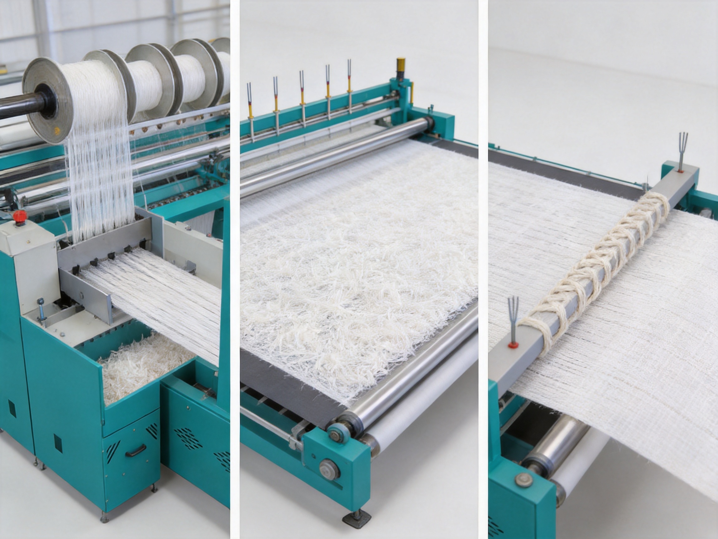
The first stage is the controlled chopping of glass fiber roving. The roving is supplied from the creel or feed arrangement and guided toward the independent cutting unit. The cutting head divides the continuous roving into short strands, with 50 mm used as the standard chopped length for the stated product configuration.
An independent chopping unit gives the line a dedicated mechanism for controlling the cutting operation. This is advantageous compared with arrangements in which fiber preparation is poorly coordinated with web formation. Stable cutting helps limit excessive variation in strand length, fiber clumping, and incomplete separation. It also allows the chopping function to be adjusted in relation to the target fabric weight and the selected roving specification.
Cutting quality is especially important when the material is intended for resin impregnation or pipeline rehabilitation. Overly long strands may create local accumulation or uneven distribution, while damaged or excessively short fibers can reduce the expected handling and reinforcement characteristics. A controlled chopping system supports a more predictable web structure.
2.2 Servo-Controlled Web Conveying
After chopping, the fibers are transported into the web-forming area. The servo-controlled conveying system is responsible for moving and distributing the chopped fibers across the working width. Servo control allows the conveying speed and material movement to be coordinated with the chopping rate and stitch-bonding parameters.
The primary objective is to produce an even web before reinforcement. If the web is too heavy in one area and too light in another, the finished fabric may show weight variation, inconsistent resin absorption, or weak zones. The conveying system therefore has a direct influence on the final product’s uniformity.
Compared with a manually adjusted or less integrated transport arrangement, servo-controlled conveying offers more precise repeatability. It also makes it easier for operators and engineers to reproduce a proven production recipe. Once the appropriate relationship between fiber feed, conveyor movement, and stitch formation has been established, the settings can be documented and applied to subsequent production runs.
2.3 Single Guide Bar Stitch Bonding
The final stage is stitch bonding. The loose chopped-fiber web enters the knitting section, where knitting yarn is formed into loops by a single guide bar. These loops pass through or around the fiber web and hold the material together as a continuous textile.
Stitch bonding provides handling strength without requiring the chopped fibers to be woven into a fixed directional structure. The finished mat can be wound, transported, cut, laminated, impregnated, or installed as part of a larger composite process. The knitting yarn also helps preserve the integrity of the web during downstream handling.
The single guide bar configuration provides a relatively straightforward base structure for manufacturers that require a stable stitch-bonded mat. It can be configured according to the required fabric weight, yarn specification, and stitch parameters. The exact loop formation arrangement is confirmed during the engineering and commissioning stages.
2.4 Coordinated Process Control
The three stages cannot be evaluated independently. A high chopping rate does not automatically produce high output if the conveyor cannot distribute the fibers evenly. Similarly, a fast stitch-bonding section cannot compensate for an irregular web. The FC machine is therefore designed as a coordinated production system in which each stage supports the next.
This integration is one of the machine’s main advantages over fragmented production arrangements. It reduces unnecessary material movement, makes the line easier to monitor, and allows the manufacturer to evaluate fiber preparation, web distribution, and stitch bonding as one process. The result is a more direct relationship between machine settings and fabric performance.
3. Advantages for Fiberglass Textile Manufacturers
The FC Chopped Stitch Bonding Machine offers several advantages for manufacturers comparing different methods of producing non-oriented fiberglass mats. These advantages relate to process integration, uniformity, product flexibility, output, engineering support, and production stability.
3.1 Integrated Production in a Single Line
The three-in-one architecture eliminates the need to move a loose chopped web between independent chopping, laying, and bonding stations. Fewer transfers can reduce handling labor and lower the risk of disturbing the web before it is secured.
Integrated production also simplifies process responsibility. Instead of coordinating several unrelated machines, the manufacturer can manage the principal operations through one connected line. This can make troubleshooting more systematic because operators can examine the relationship between chopping, conveying, and stitch bonding in sequence.
3.2 High Web Uniformity
The machine is designed to maintain a uniformity tolerance within ±5% under appropriate process conditions. This performance target is important for composite and pipeline rehabilitation applications, where local variation in areal weight can influence resin consumption, impregnation quality, mechanical performance, and finished surface consistency.
Uniformity depends on more than machine speed. Roving tex, chopping quality, conveyor settings, web distribution, stitch density, knitting yarn, and line stability all influence the final result. The FC machine addresses these variables through the combination of an independent chopping unit and servo-controlled conveying system.
During commissioning, the fabric is tested at the customer’s target weight. The engineering team can check the weight across the width, examine the web structure, and adjust process parameters before production acceptance. This approach is more practical than evaluating the machine only by an unloaded running speed.
3.3 Broad Product Weight Range
A fabric weight range of 50–900 g/m² enables the machine to serve multiple product requirements. Lighter mats can be used as reinforcement or surface-support layers, while heavier structures may be selected for more demanding composite or rehabilitation applications.
The actual production range for a specific customer depends on the material and construction. For this reason, the machine should be configured after reviewing the target fabric, fiber type, roving tex, knitting yarn, production quantity, and downstream process. A technically suitable configuration is more valuable than a nominal weight range that has not been validated with the customer’s material.
3.4 Non-Oriented Chopped Fiber Structure
The chopped fibers are distributed without deliberate directional orientation. This gives the finished mat a non-oriented reinforcement structure, which can be useful where balanced coverage and consistent resin uptake are more important than a specific 0° or 90° load direction.
This feature distinguishes the FC machine from biaxial and multiaxial warp knitting equipment. Biaxial and multiaxial machines are appropriate when directional reinforcement is required. The FC machine is more suitable when the product specification calls for a chopped strand mat, a non-oriented composite mat, or a stitch-bonded pipeline rehabilitation fabric.
3.5 Flexible Working Widths
The machine is available in working widths of 3300 mm, or approximately 130 inches, and 3800 mm, or approximately 150 inches. The correct selection depends on the finished width required by the customer and the available space in the workshop.
The wider 3800 mm version can provide greater daily output under comparable operating conditions. However, width selection must also consider the creel, access routes, take-up unit, winding arrangement, foundation, operator space, and downstream equipment. A wider machine is not automatically the best solution if the factory layout cannot support efficient operation.
3.6 Process-Based Customization
The equipment can be customized around the customer’s actual production conditions. Customization may include machine layout, frame design, fiber path, module integration, creel position, take-up direction, control arrangement, and adaptation for different fiber inputs.
This approach is useful for manufacturers with an existing workshop or downstream line. The machine can be designed to fit the available floor area rather than forcing the customer to rebuild the entire facility. Interface points are confirmed during the engineering stage so that the line can be integrated with material storage, winding, transfer, and subsequent processing equipment.
3.7 Lower Risk of Intermediate Web Damage
A loose chopped-fiber web can be vulnerable to disturbance during transfer. Integrating web formation and stitch bonding in one line helps shorten the distance and time between fiber distribution and reinforcement. This can reduce the possibility of web displacement, clumping, edge irregularity, or contamination caused by unnecessary handling.
The advantage is particularly relevant for light or delicate webs. The faster the web is stabilized by stitch bonding, the easier it is to maintain the intended distribution through take-up and downstream processing.
4. Reference Performance and Production Capacity
The machine operates within a speed range of 50–1300 r/min. Speed alone does not determine output because production capacity is also influenced by fabric construction, fabric weight, roving tex, stitch parameters, material availability, changeover frequency, operator skill, and line uptime.
The following figures are reference values supplied for two product configurations. They should be used for preliminary planning rather than as guaranteed production results.
| Working Width | Machine Speed | 300 g Felt Daily Output | 300 g Mat + 400 g Fabric Daily Output |
|---|---|---|---|
| 3300 mm (130 inches) | 50–1300 r/min | 2000 kg per day | 4000 kg per day |
| 3800 mm (150 inches) | 50–1300 r/min | 2250 kg per day | 4600 kg per day |
The 3300 mm machine is suitable for customers whose finished product width, workshop dimensions, or output plan fits the narrower platform. The 3800 mm machine provides additional working width and higher reference output for customers with a larger production requirement.
Actual output may vary from the reference figures. A 300 g felt and a 300 g mat combined with 400 g of fabric do not place the same demands on fiber feed, web distribution, stitch bonding, or take-up. Heavier structures may require lower operating speed or different material settings. Some fabrics may also need additional inspection or winding time.
For accurate capacity planning, manufacturers should provide the target fabric weight, product width, daily output objective, working schedule, fiber specification, knitting yarn, and expected product mix. The machine can then be evaluated against the intended production program rather than against a single theoretical speed.
5. Product Applications
5.1 Chopped Strand Mat
Chopped strand mat is one of the primary products of the FC machine. The glass fiber roving is cut into short strands and distributed into a non-oriented web. Stitch bonding provides sufficient integrity for handling, storage, and further composite processing.
Chopped strand mat is commonly selected where manufacturers need a conformable reinforcement layer that can be impregnated with resin. The non-oriented structure allows the material to follow curved or irregular surfaces more easily than some directional reinforcement fabrics.
5.2 Grid Composite Mat
The machine can also be used for grid composite mat production. Depending on the detailed configuration, the chopped web may be combined with a grid or complementary reinforcement structure to create a composite material with improved handling and reinforcement characteristics.
Grid composite products are often selected when the manufacturer needs a combination of distributed chopped fiber and a more organized support structure. The specific product design, grid arrangement, stitch pattern, and material combination should be confirmed during the technical proposal stage.
5.3 Pipeline Rehabilitation Fabric
Pipeline rehabilitation is a major application field for the FC machine. Rehabilitation systems often require textile materials that can be impregnated with resin, positioned inside or around a damaged pipeline, and cured to form a renewed structural lining.
A stitch-bonded chopped glass fiber mat can provide several useful characteristics for this application. The non-oriented fiber distribution supports broad-area reinforcement, while the knitting yarn helps the material retain its shape during handling and installation. Controlled fabric weight can also help maintain consistent resin uptake from one section of the lining to another.
Pipeline rehabilitation fabric must be evaluated as part of a complete lining system. Resin type, curing method, liner design, installation method, pressure conditions, temperature, and required mechanical performance all affect the final specification. The FC machine provides the textile manufacturing platform, while the final product must be validated according to the customer’s rehabilitation process.
5.4 General Composite Reinforcement
The machine is also suitable for composite reinforcement manufacturers producing non-oriented fiberglass mats for industrial parts, panels, lining systems, construction products, and other applications. The appropriate fabric weight and stitch structure depend on the required handling, impregnation, thickness, flexibility, and mechanical performance.
6. Engineering and Manufacturing Strengths
The performance of a stitch-bonding machine depends not only on its basic design but also on the quality of the manufacturing process behind it. Changzhou Yuanyang Electromechanical Technology Co., Ltd. combines research and development, mechanical fabrication, electrical integration, testing, installation, and service support.
6.1 Dedicated Textile Machinery Engineering
The company operates from an engineering and manufacturing base in Jiangsu, China, covering more than 12,000 square meters. Its annual production capacity exceeds 200 sets of equipment. This production scale supports the development of standardized machine platforms while retaining the flexibility required for non-standard configurations.
The engineering team focuses on warp knitting machinery and related equipment, including stitch-bonding machines, biaxial and multiaxial machines, carbon fiber textile machinery, powder scattering machines, web laying machines, and specialized accessories. This broader technical background helps the company understand how the FC machine may connect with other textile and composite production systems.
6.2 Research and Development Capability
The company’s research and development team includes experienced industry engineers who work on structural design, machine performance, process adaptation, and product improvement. This capability is important for customers whose requirements do not match a standard catalogue configuration.
Examples of engineering work may include the redesign of machine frames, adaptation of material paths, integration of auxiliary modules, adjustment of control systems, and development of equipment for difficult-to-process fibers. The company also handles complex fabric designs and production lines requiring long-term stability.
6.3 Mechanical Manufacturing and Assembly
Machine quality is influenced by the accuracy of components, alignment of moving sections, rigidity of the frame, reliability of drive systems, and precision of assembly. The manufacturing process includes component procurement, machining, mechanical assembly, electrical installation, debugging, and factory testing.
Before shipment, the machine is assembled and tested at the production base. No-load operation is checked first, followed by process-related testing and fabric trials where applicable. These activities help identify mechanical, electrical, and control issues before the equipment reaches the customer’s factory.
6.4 Electrical and Servo Control Integration
The servo-controlled conveying system is a central part of the FC machine. Electrical integration must coordinate conveying speed, chopping operation, stitch-bonding movement, safety functions, and operator controls.
A well-integrated control system allows the operator to adjust the process in a controlled manner and supports repeatable production. It also helps engineers document process parameters for different fabric constructions. The exact electrical configuration is determined by the machine specification, customer standards, site conditions, and required automation level.
6.5 Quality Control at Multiple Stages
Quality control is applied throughout the build rather than only at final inspection. Incoming components and materials are inspected before use. Machining and assembly are monitored during production. Electrical connections and control functions are checked before commissioning.
Completed machines undergo no-load and load running tests. Fabric trials are used to verify fiber distribution, weight, stitch formation, and uniformity. This process-based inspection helps ensure that the equipment is not merely assembled but also capable of producing the required textile under realistic conditions.
| Control Stage | Main Purpose |
|---|---|
| Incoming inspection | Verify components, materials, and purchased parts before production use. |
| Machining and fabrication control | Maintain dimensional accuracy and structural quality. |
| Mechanical assembly inspection | Check alignment, fastening, movement, and installation accuracy. |
| Electrical and control testing | Verify wiring, drives, sensors, control functions, and safety systems. |
| No-load running test | Confirm smooth machine operation before material is introduced. |
| Fabric trial | Evaluate chopping, web distribution, stitch bonding, weight, and uniformity. |
| Final inspection | Confirm readiness for packing, dispatch, installation, and acceptance. |
7. Configuration and Line Integration
A successful installation begins with accurate information about the customer’s factory, raw materials, products, and downstream processes. The FC machine is configured according to the working point rather than selected only by nominal width or speed.
7.1 Fiber Input
The standard input is glass fiber roving. Roving tex, package format, creel arrangement, fiber tension, and feed direction affect the design of the material path and the chopping unit. Customers should provide the fiber data they intend to use so that the cutting and conveying system can be evaluated correctly.
7.2 Fabric Specification
The target fabric weight and width determine the required material feed, stitch settings, take-up arrangement, and operating conditions. If the customer plans to produce several weights, the machine should be reviewed against the complete product range rather than only the lightest or heaviest specification.
7.3 Knitting Yarn
Knitting yarn affects loop formation, fabric handling, and finished textile stability. Yarn count, material, package format, and required stitch density should be discussed during configuration. The guide bar and related knitting components can then be selected or adjusted according to the intended product.
7.4 Workshop Layout
Available floor space affects the machine frame, creel position, operator access, take-up direction, maintenance area, and material flow. The installation drawing should include not only the main machine but also the space required for raw material loading, finished roll removal, inspection, cleaning, and service access.
7.5 Downstream Interface
The finished mat may be wound, cut, laminated, impregnated, or transferred to another production stage. The FC machine must therefore be coordinated with the downstream equipment. Take-up speed, roll dimensions, transfer direction, edge control, and finished-roll handling are considered during the engineering stage.
7.6 Utilities and Site Conditions
Power supply, compressed air, foundation requirements, ventilation, lighting, temperature, humidity, and material storage conditions can affect installation and operation. Confirming these details in advance reduces delays during commissioning and helps the customer prepare the workshop properly.
8. Installation, Commissioning, and Acceptance
The machine is tested before delivery and then installed and commissioned at the customer’s factory. An engineer attends the site to support mechanical assembly, electrical connection, process adjustment, trial production, and operator training.
- Review the foundation, workshop layout, access route, and leveling conditions.
- Position the machine and complete mechanical assembly.
- Align the major components and connect the drive system.
- Complete electrical wiring, control connections, and safety checks.
- Run the machine without material to confirm movement and control functions.
- Thread the glass fiber roving and knitting yarn according to the approved process.
- Calibrate chopping and conveying parameters.
- Produce trial fabric at the target weight and width.
- Measure fabric weight and assess web uniformity across the working width.
- Train operators and maintenance personnel.
- Document production parameters and acceptance results.
Acceptance should be connected to the customer’s actual target fabric. Relevant criteria may include finished weight, width, fabric appearance, stitch formation, uniformity, operating stability, and production speed. This is more meaningful than accepting a machine solely on the basis of an empty running speed.
The commissioning team can assist with parameter adjustment when the customer changes product weight, fiber tex, knitting yarn, or stitch density. Production staff are shown how to recognize common issues such as uneven web distribution, fiber accumulation, excessive edge variation, irregular stitch formation, and abnormal machine vibration.
9. Maintenance, Training, and Long-Term Support
Regular maintenance is essential for stable fiberglass textile production. Glass fiber can create abrasive dust, and cutting operations place wear on blades and related components. Knitting elements and web transport parts also require inspection and replacement at appropriate intervals.
9.1 Key Maintenance Areas
- Chopping blades and cutting surfaces.
- Fiber guides and material path components.
- Conveyor surfaces, rollers, and drive elements.
- Knitting needles, guide components, and stitch-forming parts.
- Servo motors, transmission components, and couplings.
- Sensors, electrical cabinets, and control connections.
- Take-up and winding equipment.
- Dust removal and cleaning systems.
Maintenance intervals depend on running hours, fiber type, product weight, environmental conditions, and production intensity. A preventive maintenance schedule should include daily cleaning, regular lubrication where specified, inspection of wear parts, checking of fasteners, and review of drive and control alarms.
9.2 Maintainer Training
Maintenance personnel can receive practical training at the manufacturer’s factory. The training may cover installation participation, mechanical adjustment, troubleshooting, wear-part replacement, cleaning, lubrication, and safe working procedures. The stated training period is generally one to two months, depending on the customer’s requirements.
9.3 Knitter and Operator Training
Operators receive hands-on training in the fabrication workshop. The training focuses on machine operation, yarn threading, fiber threading, fabric weight adjustment, stitch settings, product changeover, routine inspection, and safe response to abnormal conditions.
Practical training is especially valuable for stitch-bonding machinery because product quality depends on the relationship between mechanical movement and material behavior. Operators should understand not only which button to press but also how a change in fiber feed or conveyor speed affects the finished web.
9.4 Workshop Management Training
Supervisors and production managers can receive training in quality control, production planning, process parameter management, output tracking, and documentation. This training generally lasts one to two months when required.
The company can also help customers establish and compile quality system documents. These may include production records, maintenance schedules, inspection forms, material traceability documents, process parameter sheets, and acceptance reports.
9.5 Spare Parts and Technical Assistance
Spare parts support covers the components most likely to experience wear during long-term production, including chopping blades, knitting elements, guides, transport components, and selected electrical or drive parts. Maintaining an appropriate spare-parts inventory can reduce downtime and improve response to urgent maintenance needs.
After-sales engineers remain available to assist with production problems throughout the equipment’s working life. Support may involve remote troubleshooting, process recommendations, replacement-part identification, production analysis, and on-site service when necessary.
10. Comparison with Alternative Reinforcement Production Methods
The FC Chopped Stitch Bonding Machine should be compared with alternative technologies according to the required reinforcement structure, not only according to machine speed. Different textile processes produce different material characteristics.
10.1 Compared with Conventional Loose Chopped Mat Lines
A conventional loose chopped mat line may form a fiber web and rely on a separate binder or subsequent consolidation process. The FC machine uses stitch bonding to reinforce the web with knitting yarn. This can provide improved handling strength and a more textile-like structure while avoiding reliance on a separate chemical binder system in the basic stitch-bonding operation.
The integrated chopping, conveying, and stitch-bonding arrangement also reduces the number of intermediate transfers. This can improve process coordination and reduce disturbance of the loose web before reinforcement.
10.2 Compared with Woven Fiberglass Fabrics
Woven fabrics have fixed warp and weft directions, while the FC machine produces a non-oriented chopped-fiber mat. Woven reinforcement is appropriate when directional strength, dimensional geometry, and a defined yarn architecture are required. Chopped stitch-bonded mat is more appropriate when conformability, distributed reinforcement, and broad-area coverage are priorities.
10.3 Compared with Biaxial Warp Knitting Machines
Biaxial warp knitting machines produce reinforcement in defined directions such as 0° and 90°. They are suitable for structural composite designs requiring directional load transfer. The FC machine is intended for chopped fiber mats and non-oriented structures. Choosing between the two depends on whether the final product needs directional reinforcement or a distributed chopped-fiber architecture.
10.4 Compared with Multiaxial Reinforcement Equipment
Multiaxial equipment is designed for several organized reinforcement directions and is often used for high-performance composite laminates. The FC machine is simpler in product concept and is focused on chopped strand mats, grid composite mats, and rehabilitation fabrics. Its advantage is process suitability for these products rather than universal replacement of multiaxial machinery.
10.5 Compared with Separate Chopping and Stitch-Bonding Lines
Using separate machines may provide flexibility for factories that already have established equipment, but it can introduce additional transfer, labor, floor-space, and coordination requirements. The FC machine’s integrated configuration is advantageous for new lines or manufacturers seeking to consolidate operations.
The most suitable technology depends on the customer’s product specifications, output target, available workshop, labor model, fiber type, and downstream process. A technical consultation is therefore recommended before selecting the machine architecture.
11. Recommended Data for a Technical Proposal
Customers can accelerate the engineering and quotation process by preparing complete production information. The following data helps determine the appropriate configuration.
| Required Information | Why It Matters |
|---|---|
| Target fabric and weight range | Determines fiber feed, web density, stitch parameters, and process range. |
| Fiber type and roving tex | Influences cutting head setup, material path, and conveying requirements. |
| Required working width | Supports selection between 3300 mm and 3800 mm configurations. |
| Daily or annual output target | Helps determine line speed, working schedule, and line balancing. |
| Knitting yarn specification | Influences guide bar configuration and loop formation. |
| Workshop drawings and floor space | Determines machine layout, creel location, access, and take-up direction. |
| Downstream process | Defines winding, transfer, impregnation, cutting, or lamination interfaces. |
| Utilities and site conditions | Confirms power supply, compressed air, foundation, and installation needs. |
| Fabric samples or technical drawings | Allows the engineering team to evaluate the proposed construction. |
For non-standard configurations, the project may proceed through drawing review, sample analysis, preliminary design, three-dimensional drawing confirmation, quotation, production, inspection, and delivery. This engineering sequence is useful when the customer has a complex fabric design, a difficult material, limited workshop space, or a special downstream requirement.
12. Frequently Asked Questions
What products can the FC Chopped Stitch Bonding Machine manufacture?
The machine is designed for chopped strand mat, grid composite mat, and pipe rehabilitation fabric. It is also suitable for other non-oriented stitch-bonded fiberglass reinforcement products when the material and construction fall within the machine’s process capabilities.
What type of fiber does the standard machine use?
The standard machine uses glass fiber roving. The roving is cut into 50 mm strands and distributed into a web before stitch bonding. Adaptation for synthetic fiber or carbon fiber inputs may be considered as an engineering project after reviewing the material characteristics and required process conditions.
What fabric weight range is available?
The stated fabric weight range is 50–900 g/m². The precise achievable range depends on the fiber tex, material feed, chopping rate, web distribution, knitting yarn, stitch density, and operating speed. Product trials are recommended for a specific customer material and construction.
How is fabric uniformity controlled?
Uniformity is supported by the independent chopping unit and servo-controlled conveying system. The conveying system distributes the chopped fibers evenly before stitch bonding. Under suitable operating conditions, the stated uniformity tolerance is within ±5%. Final verification is carried out during fabric trials and commissioning.
What is the standard chopped fiber length?
The standard chopped fiber length is 50 mm. Other cutting requirements may require a technical review of the chopping unit, fiber type, roving tex, and finished product specification.
Which working width should be selected?
The machine is available in 3300 mm and 3800 mm working widths. The choice depends on the finished mat width, planned output, workshop space, creel arrangement, take-up system, and downstream production line. The wider version offers higher reference daily output under comparable conditions.
What are the reference output figures?
For a 3300 mm working width, the reference output is 2000 kg per day for 300 g felt and 4000 kg per day for 300 g mat plus 400 g fabric. For a 3800 mm working width, the reference output is 2250 kg per day for 300 g felt and 4600 kg per day for 300 g mat plus 400 g fabric. These figures are for planning reference only and may vary according to the actual product and process.
Is the machine suitable for pipeline rehabilitation fabric?
Yes. Pipeline rehabilitation fabric is one of the machine’s principal application areas. The stitch-bonded chopped glass fiber structure can provide a conformable, non-oriented reinforcement layer for resin-based lining systems. Final suitability must be confirmed according to the complete rehabilitation system and applicable technical requirements.
Can the machine be integrated into an existing workshop?
Yes. Layout, frame arrangement, creel position, fiber path, take-up direction, and downstream interfaces can be adapted to the customer’s workshop. Accurate floor plans, access information, utility conditions, and equipment interface drawings should be provided before final design approval.
Can the machine produce carbon fiber or synthetic fiber products?
The standard FC configuration is intended for glass fiber roving. Adaptation for synthetic fiber or carbon fiber may be possible, but it requires an engineering assessment because fiber abrasiveness, brittleness, static behavior, tensile properties, and handling requirements can differ significantly.
What installation support is provided?
An engineer attends the customer’s factory for installation, commissioning, parameter adjustment, trial production, and operator training. The process includes foundation and leveling checks, mechanical assembly, electrical connection, no-load testing, material threading, fabric trials, and acceptance verification.
What training is available?
Training can be provided for maintainers, machine operators, knitters, and workshop managers. Training covers installation, operation, maintenance, fabric weight control, quality inspection, production planning, and process documentation. Factory-based training is generally available for one to two months depending on the customer’s requirements.
What should be included in the acceptance test?
Acceptance should be based on the agreed target fabric. Typical criteria include fabric weight, width, uniformity, stitch formation, stable operation, and production performance under the specified material and process settings. The exact acceptance conditions should be documented before shipment.
How does the FC machine compare with a biaxial warp knitting machine?
The FC machine produces a non-oriented chopped-fiber mat reinforced by stitch bonding. A biaxial warp knitting machine produces reinforcement in organized directions, typically 0° and 90°. The FC machine is suitable for chopped strand mat and distributed reinforcement, while biaxial equipment is more appropriate for directional structural composite designs.
How can production downtime be reduced?
Preventive maintenance, regular cleaning, timely replacement of chopping blades and knitting elements, correct material threading, and proper operator training all help reduce downtime. Keeping essential spare parts on site and recording process parameters for each product can also improve response speed during product changes or troubleshooting.
13. Conclusion
The FC Chopped Stitch Bonding Machine provides an integrated solution for the production of fiberglass chopped strand mats, grid composite mats, and pipeline rehabilitation fabrics. Its combination of independent chopping, servo-controlled conveying, and single guide bar stitch bonding allows manufacturers to convert glass fiber roving into a stable, non-oriented textile in one continuous process.
The machine’s main strengths include a broad 50–900 g/m² fabric weight range, working widths of 3300 mm and 3800 mm, a speed range of 50–1300 r/min, reference uniformity within ±5%, and process integration designed to reduce unnecessary web handling. These features make it a practical alternative to fragmented production arrangements when the target product requires a stitch-bonded chopped-fiber structure.
Its advantages are reinforced by the manufacturer’s engineering and manufacturing capabilities. Changzhou Yuanyang Electromechanical Technology Co., Ltd. combines research and development, mechanical fabrication, servo and electrical integration, quality control, factory testing, installation, commissioning, training, spare-parts support, and long-term technical service.
The correct machine configuration should be determined by the customer’s actual product, fiber material, fabric weight, production target, workshop layout, utilities, and downstream process. When these factors are reviewed together, the FC machine can be developed as a complete production solution rather than treated as an isolated piece of equipment.
For manufacturers seeking consistent non-oriented fiberglass reinforcement, efficient pipeline rehabilitation fabric production, and an adaptable stitch-bonding platform, the FC Chopped Stitch Bonding Machine offers a technically focused and scalable option.
References
1. Changzhou Yuanyang Electromechanical Technology Co., Ltd. Product information for the FC Chopped Stitch Bonding Machine.
2. Changzhou Yuanyang Electromechanical Technology Co., Ltd. Technical information on stitch-bonding machinery and fiberglass textile equipment.
3. Internal production reference data for 3300 mm and 3800 mm working-width configurations.
4. Internal process information concerning glass fiber chopping, servo-controlled conveying, single guide bar loop formation, and fabric uniformity verification.
5. General technical principles of glass fiber chopped strand mats, stitch-bonded reinforcement fabrics, and pipeline rehabilitation textile materials.
Product: FC Chopped Stitch Bonding Machine
News
-
Which Machine Category Matches Each Technical Fiber and Fabric Goal A warp knitting machine is the primary production platform for technical fiber textiles across fiberglass, chemical fiber, and carbo...
READ MORE -
We will participate in the 2023 Dhaka International Textile & Garment Machinery Exhibition, Bangladesh from February 15 to 16, 2023. We will exhibit the latest models and technologies and look for...
READ MORE -
Have you ever wondered why some weaving looms operate flawlessly for decades, while others seem to suffer from constant breakdowns and quality issues? The secret isn’t luck; it’s a disciplined and str...
READ MORE -
Warp knitting is a combination of weaving methods in which the yarns meander along the length of the fabric; that is, they follow adjacent columns or wales, rather than a single row or course. For com...
READ MORE
-
Contact Info.
+86-198 5534 1617
+86-134 0158 3002yuanyang@yywarpknitting.com 699#, Shengzhi West Rd, Lvcheng Town, Danyang City, Zhenjiang City, Jiangsu Province, China
-
QR Code
-
Quick Links
Home About Products Manufacturing Customization News Contact -
Product List
Machine for Chemical Fiber Textile Machine for Fiberglass Textile Machine for Carbon Fiber Textile -
About Us
Company Profile Factory Gallery Value-added Service
Copyright © 2026 Changzhou Yuanyang Electromechanical Technology Co., Ltd. All Rights Reserved.
Custom Warp Knitting Machine Manufacturers
